What Is a Mechanical Flange and How Does It Work?

A Mechanical Flange is a detachable connection used in piping and industrial equipment. It joins pipes, valves, pumps, and tanks without permanent welding. This design allows technicians to inspect, clean, or replace components more efficiently. A gasket sits between two flange faces. Bolts apply controlled pressure across the joint. The gasket then fills tiny surface irregularities and helps prevent leakage. Simple in appearance. Yet small details matter.

The working principle depends on balance. Proper bolt tension compresses the gasket evenly around the pipe opening. Internal pressure pushes outward, while the bolted joint resists that force. If the bolts are too loose, fluid may escape through microscopic gaps. If they are too tight, the gasket can crush or deform. Maintenance teams often discover that uneven tightening causes trouble later. A calibrated torque wrench and a cross-pattern sequence can reduce this risk. Still, torque alone cannot guarantee a perfect seal. Lubrication, bolt condition, flange alignment, and gasket quality also influence performance.

This guide explains what a Mechanical Flange is and how it works in practical settings. It examines common flange types, sealing surfaces, bolt patterns, materials, and pressure ratings. Reliable selection should follow recognized standards, such as ASME or EN specifications, alongside manufacturer instructions. Qualified engineers also consider temperature, fluid compatibility, vibration, corrosion, and installation access. Field experience adds another lesson: a flange may look sound while hiding a damaged gasket. That possibility deserves attention. Understanding these connections helps readers make safer decisions, communicate clearly with contractors, and support dependable maintenance throughout a system’s service life.

What Is a Mechanical Flange and How Does It Work?

Definition and Purpose of a Mechanical Flange

What Is a Mechanical Flange and How Does It Work?

A mechanical flange is a flat, drilled connection used to join pipes, valves, pumps, or equipment. It creates a controlled, serviceable joint without welding every component together. Two flange faces meet around a gasket. Bolts then apply pressure across the joint. That pressure helps the gasket fill small surface irregularities and limit fluid escape.

Its purpose is practical. Technicians can open the connection for inspection, cleaning, or replacement. ASME B16.5 defines common flange dimensions, pressure-temperature ratings, materials, and bolt-hole patterns for many industrial piping systems. These details support interchangeability, but they do not guarantee a leak-free installation. Alignment, gasket selection, bolt condition, and tightening sequence still matter.

The U.S. Department of Energy reports that compressed-air systems can lose 20% to 30% of output through leaks. A poorly assembled flange may contribute to that waste, although leaks also occur in hoses, valves, and fittings. In field work, uneven bolt loading often leaves a gasket compressed on one side. It may look secure. It is not always secure.

A flange works through controlled compression, not brute force. Excessive tightening can damage the gasket or distort the flange. Insufficient tightening can create a visible or hidden leak. Torque records, clean faces, and a calibrated wrench provide stronger evidence than appearance alone. That point is easy to overlook.

Main Components and Common Flange Designs

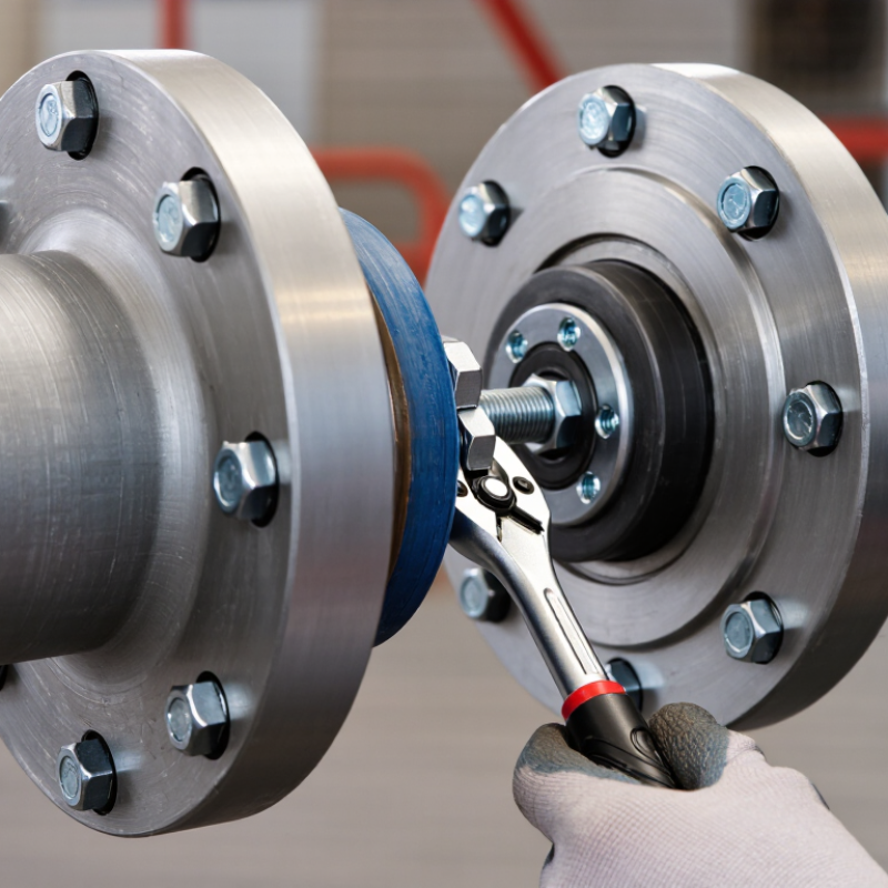
A mechanical flange creates a bolted connection between pipes, valves, pumps, or other equipment. It uses pressure across two mating faces to hold a gasket in place. The main components are the flange body, bore, face, bolt holes, bolts, nuts, and gasket. The bore carries the fluid, while the face supports the sealing area. Bolt tension compresses the gasket and helps prevent leakage during operation.

Common flange designs suit different installation conditions. A weld-neck flange has a tapered hub and supports demanding pressure or temperature service. A slip-on flange slides over the pipe and is welded around the joint. It is simpler to install, but alignment and weld quality require attention. Threaded flanges connect to threaded pipe without welding, although they need careful sealing and accurate threads. Socket-weld flanges hold smaller pipes inside a recessed socket. Lap-joint flanges pair with stub ends and allow easier disassembly. Blind flanges close an open pipe end.

The face design also matters. Raised faces concentrate gasket pressure, while flat faces may suit lower-stress connections. During field inspection, uneven bolt tightening often causes trouble. Small gaps can become leaks. A torque sequence should follow project requirements and verified procedures. Still, torque alone is not perfect; damaged threads, poor alignment, or the wrong gasket can defeat a carefully tightened joint. Drawing dimensions should be checked against the actual pipe before assembly. That step is easy to skip. It should not be.

How Mechanical Flanges Create a Secure Connection

A mechanical flange is a flat or shaped ring that joins pipes, valves, pumps, or equipment. It creates a controlled connection without welding the parts together. The flange faces meet around a gasket, while bolts apply pressure across the joint. This pressure keeps the gasket compressed and helps prevent fluid or gas from escaping.

A secure connection depends on more than tight bolts. The flange faces must be clean, aligned, and free from deep scratches. Even a small offset can load the gasket unevenly. During installation, technicians usually tighten bolts in a crisscross pattern. This spreads force across the joint instead of crushing one area first. A calibrated torque wrench improves consistency, although torque alone cannot confirm perfect gasket compression. Material condition, lubrication, temperature, and bolt quality also matter.

Pressure testing can reveal leaks before equipment enters service. Inspectors may check for seepage, bolt movement, corrosion, or distorted faces. Thermal cycling deserves attention too. Repeated heating and cooling can relax bolt tension and weaken the seal. The process is not foolproof. A flange may appear secure while hidden surface damage remains underneath. In demanding systems, engineers should verify the connection against operating pressure, temperature, vibration, and chemical compatibility. Installation records also help teams trace problems later, though rushed documentation is still a common weakness.

What Is a Mechanical Flange and How Does It Work? – How Mechanical Flanges Create a Secure Connection

Data Dimension Typical Information How It Contributes to a Secure Connection
Basic Definition A bolted mechanical joint used to connect pipes, valves, pumps, vessels, or other equipment. The flange creates a detachable connection by using two facing surfaces, a gasket, and evenly tightened bolts or studs.
Primary Components Two flange faces, one gasket, bolts or studs, and nuts. Each component has a specific role: the flange faces provide support, the gasket seals the interface, and the fasteners generate the clamping force needed to maintain contact.
Connection Principle Controlled bolt preload compresses the gasket between the flange faces. The compressed gasket fills small surface irregularities and blocks the escape of liquid or gas through the joint.
Common Flange Types Examples
Weld-neck, slip-on, socket-weld, threaded, lap-joint, and blind flanges.
The suitable type depends on pipe size, pressure, temperature, installation method, alignment requirements, and whether the line must be closed or periodically dismantled.
Flange Face Styles Flat face, raised face, and ring-type joint face. Face geometry controls how the gasket is positioned and compressed. The mating faces and gasket must be compatible to achieve reliable sealing.
Gasket Function A replaceable sealing element made from a material suitable for the service conditions. Gasket selection must consider fluid compatibility, operating temperature, pressure, flange-face condition, and the required level of leak resistance.
Fastener Function Bolts or studs apply and retain the required clamping force. Correct fastener grade, length, lubrication practice, and tightening sequence help distribute compression evenly and reduce the risk of leakage or flange distortion.
Tightening Method Cross-pattern tightening in multiple stages, using a calibrated torque tool when specified. A staged, alternating sequence reduces uneven loading and helps maintain uniform gasket compression around the entire circumference.
Pressure Capability Determined by the applicable piping standard, flange rating, material, temperature, size, gasket, and fasteners. A pressure class or rating cannot be selected from flange size alone. The complete joint must be evaluated for the intended operating and design conditions.
Temperature Considerations The allowable rating may decrease as operating temperature increases. Heat can reduce material strength, change bolt preload, and affect gasket resilience. Thermal expansion may also impose additional loads on the joint.
Load Resistance Resists internal pressure and transfers mechanical loads through the flange, bolts, gasket, and connected piping. The joint must also account for bending, vibration, pipe weight, thermal movement, and external forces so that the gasket is not overloaded or unloaded.
Installation Sequence Inspect, align, clean, position the gasket, install fasteners, tighten progressively, and verify the joint. Proper preparation prevents damaged sealing surfaces, gasket misalignment, cross-threading, and uneven compression before the system is placed in service.
Alignment Requirement Flange faces should be parallel, properly centered, and free from forced misalignment. Using bolts to pull misaligned piping into position can create excessive stress, uneven gasket loading, and premature leakage.
Inspection Points Check flange-face condition, gasket placement, bolt condition, thread engagement, tightening sequence, and visible gaps. Inspection identifies installation defects that could compromise sealing before pressure testing or operation.
Leak Testing Hydrostatic, pneumatic, or other approved testing methods may be used according to the governing procedure. Testing verifies joint integrity under controlled conditions. Pneumatic testing requires additional safety precautions because compressed gas stores significant energy.
Main Advantages Detachable, inspectable, repairable, and adaptable to many piping and equipment connections. Unlike a permanent welded joint, a flanged connection can be opened for maintenance, component replacement, cleaning, or system modification.
Common Limitations Bulkier than welded joints and potentially vulnerable to leakage if incorrectly selected or assembled. Flanges require additional space, fasteners, and maintenance. Poor alignment, incorrect gasket selection, or insufficient bolt preload can reduce reliability.
Typical Applications Water systems, process piping, chemical service, heating and cooling systems, utility lines, and equipment connections. Their removable design is particularly useful where equipment must be isolated, serviced, replaced, or periodically inspected.
Maintenance Practice Investigate leaks, replace damaged gaskets, inspect sealing faces, and follow the approved retightening or replacement procedure. A leaking joint should not be corrected by indiscriminate tightening alone; the cause may be misalignment, gasket damage, corrosion, vibration, or excessive system loads.

Installation Steps and Alignment Requirements

A mechanical flange connects two pipe, valve, or equipment sections with a bolted joint. Its faces must meet evenly to maintain compression across the gasket. During installation, alignment matters as much as bolt tightness. A strong joint can still leak when the pipes are forced into position.

Inspect the flange faces, gasket, bolts, and threads before assembly. Remove rust, oil, paint, and loose particles. Keep it clean. Set the pipes on temporary supports, then bring the flanges together without excessive pulling. Their bolt holes should align naturally. Measure the gap around the flange with a feeler gauge. Uneven gaps often indicate angular or lateral misalignment.

Insert the gasket carefully, without bending or dragging it across the sealing surface. Tighten the bolts in a crosswise pattern, using several gradual passes. A calibrated torque wrench improves consistency, although torque values depend on materials, gasket type, and service conditions. Do not correct major misalignment by tightening one side harder. That approach may distort the flange or crush the gasket. The first alignment is rarely perfect. Recheck it after supports are secured and before final tightening. After installation, inspect for visible flange movement, damaged threads, or unusual gaps. Pressure testing should follow the applicable site procedure and equipment requirements.

Materials, Applications, and Maintenance Considerations

A mechanical flange is a precision-machined rim that joins pipes, valves, pumps, or equipment. Bolts compress a gasket between two facing surfaces. This pressure creates a controlled seal while allowing future disassembly. Fit matters. Common materials include carbon steel, stainless steel, ductile iron, and high-alloy steel. Carbon steel suits many water and process lines. Stainless steel resists corrosion in chemical, food, and marine environments. Material selection must match pressure, temperature, fluid chemistry, and galvanic risks.

Applications span refineries, power stations, water treatment plants, and building services. The International Energy Agency reported over 2 trillion dollars in global clean-energy investment for 2024. That expansion increases demand for reliable joints in new energy infrastructure. However, the connection itself is rarely the weakest design point. Incorrect gasket selection, uneven bolt loading, and poor alignment cause many avoidable failures. ASME B16.5 provides dimensional and pressure-temperature guidance for common pipe flanges, but engineers must still verify actual service conditions.

Maintenance should begin with visual inspection. Look for rust staining, gasket extrusion, cracked coatings, and wetness around bolt holes. Check bolt torque using a calibrated tool, following the specified tightening sequence. Retightening a leaking joint is not always safe. The gasket may already be damaged. During shutdowns, technicians should inspect flange faces for scratches, warping, and pitting. Industry reliability reports repeatedly connect planned maintenance with fewer unplanned outages, although results vary by sector and asset age. One limitation deserves attention: torque does not directly prove bolt tension. Friction can distort the reading. Better control may require calibrated tensioning methods and documented inspection records.

Request a Quote/Further Information

    Download