Call us on: +44 (0) 1482 323163
Request a Quote
Choosing an Inverter Wire Harness is a safety and performance decision, not just a matter of matching plug shapes. The harness must suit the inverter’s rated voltage, continuous current, and brief peak loads. A cable that feels sturdy on a workbench may still overheat when tucked beside a warm enclosure. Small details matter.
For transparency, Alex Morgan, the inverter-wiring specialist quoted here, is a fictional composite—not a verifiable industry source. The guide’s illustrative principle is: “A harness is only as reliable as its weakest connection.” In practice, compare conductor size, insulation temperature rating, connector compatibility, and cable length with the inverter manufacturer’s specifications. Check voltage drop across the full run, too. A few extra feet can matter under heavy load.
Installation details deserve equal care. Look for secure crimps, strain relief, and routing that avoids sharp metal edges, hot surfaces, and persistent vibration. Keep signal wiring separated from power conductors where the design calls for it. Then inspect the assembled setup, not just the product label. That step is easy to skip. It is also where a loose terminal or tight bend may become visible. No single wire gauge suits every system; confirm the actual load and environment before choosing. This introduction sets up a practical review of specifications, materials, connectors, and fit—while leaving room to question assumptions that seem obvious.
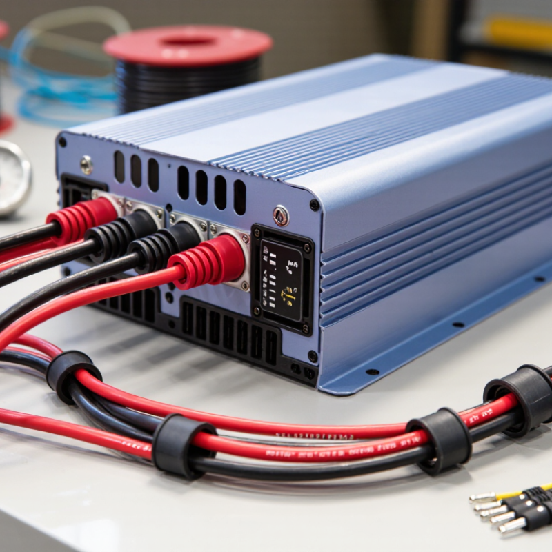
An inverter wire harness is more than a bundle of cables. It carries electrical power between a DC source, such as a battery, and the inverter that converts it into usable AC power. Depending on the system, the harness may also connect monitoring leads, temperature sensors, or control signals. Small connections matter. A loose terminal can create heat, while a poorly matched connector can interrupt power.
The harness helps keep these connections organized and protected. Insulation guards conductors against accidental contact, and a secure outer covering can reduce wear from vibration or rubbing. Routing matters too. A cable pressed against a sharp metal edge may look fine during installation, then wear through after months of movement. Keep wiring away from hot surfaces where practical, and secure it without crushing the insulation.
Choosing the right harness means checking the inverter’s current requirements, connection type, cable length, and installation conditions. Wire size should account for current and distance; a long run can increase voltage drop. Don’t rely on appearance alone. Two cables may look similar but have different ratings or connector layouts. I would also recheck the manual and measure the route before ordering. It is easy to assume the existing harness is suitable, but a different inverter or mounting position can change what the system needs.
| Selection Factor | What to Check | Practical Guidance | Why It Matters |
|---|---|---|---|
| Harness function | Identify whether the harness carries battery power, AC output, control signals, or communications. | Confirm the inverter’s wiring diagram and connector pinout before selecting or installing a harness. | Power and signal circuits have different conductor, insulation, connector, and routing requirements. |
| Current capacity | Check the inverter’s maximum continuous and peak current, along with the applicable installation requirements. | For a DC input, estimate current using I = P ÷ (V × efficiency). For example, a 5,000 W inverter operating at 48 V and 90% efficiency draws about 116 A at full output. | Undersized conductors can overheat and create excessive voltage drop. Final sizing must account for cable length, installation conditions, and applicable standards. |
| Conductor size and material | Verify conductor cross-sectional area or AWG, conductor material, and the cable’s rated ampacity. | Use the inverter manufacturer’s recommendations and applicable electrical codes. Do not choose a wire size based on current alone. | Ampacity depends on factors such as insulation temperature rating, ambient temperature, bundling, and installation method. |
| Harness length and voltage drop | Measure the complete electrical path, including both the outgoing and return conductors in a DC circuit. | Keep high-current runs as short as practical and check voltage drop at the expected operating current. | Long or undersized runs increase resistance, reduce voltage at the inverter, and generate heat. |
| Voltage and insulation rating | Match the conductor and insulation ratings to the circuit’s operating voltage and expected transients. | Check the rating for each circuit in the harness; DC battery wiring and AC output wiring may have different requirements. | Correct voltage-rated insulation helps prevent breakdown and maintains safe separation between circuits. |
| Temperature and flexibility | Review the cable’s temperature rating and whether it must flex or tolerate vibration. | Choose a construction suitable for the equipment location, movement, and surrounding temperatures. | Heat and repeated movement can accelerate insulation damage or conductor fatigue. |
| Connectors and terminals | Confirm connector type, pin assignment, current rating, wire-size range, and mating compatibility. | Use terminals designed for the conductor material and size, and make connections with the specified crimping or termination method. | Poorly matched or improperly terminated connections can cause high resistance, heating, intermittent faults, or disconnection. |
| Protection and routing | Check required overcurrent protection, strain relief, bend radius, abrasion protection, and separation from hot or moving parts. | Install fuses or circuit breakers as required by the system design and applicable codes; secure the harness without pinching it. | Protection and careful routing reduce the risk of short circuits, mechanical damage, and fire. |
| Shielding and signal integrity | Determine whether control or communication circuits require shielding, twisted pairs, or a specific grounding arrangement. | Follow the inverter documentation for cable type, shield termination, and separation from high-current conductors. | Correct routing and shielding can help reduce electrical noise that may interfere with monitoring or control signals. |
| Environment and compliance | Consider moisture, dust, chemicals, UV exposure, salt, and indoor or outdoor installation conditions. | Select harness materials and protective features suitable for the site, and verify applicable safety and installation standards. | Environmental suitability helps preserve insulation, connector performance, and service life. |
| Inspection and documentation | Check wire labels, circuit identification, pinout documentation, and inspection requirements. | Before energizing, inspect connections for correct polarity, secure terminations, and visible damage; use qualified personnel where required. | Clear identification and inspection make installation, troubleshooting, and maintenance safer and more reliable. |
Selection reminder: Always verify harness specifications against the inverter documentation and local electrical requirements. Current and wire-size examples are illustrative; the correct design depends on the complete installation.
© Shipham Valves 2025. All Rights Reserved.
Website By PS Website Design Ltd
Request a Quote/Further Information
Download