Call us on: +44 (0) 1482 323163
Request a Quote
Choosing a Three-Axis Servo Robot in 2026 is no longer a simple speed comparison. A production line may demand fast indexing, stable positioning, quiet motion, and reliable integration with vision systems. The wrong choice can leave an expensive machine waiting beside an underused conveyor.
The International Federation of Robotics reported 541,302 industrial robots were installed worldwide in 2023. Its World Robotics 2024 report also recorded more than 4.28 million industrial robots operating globally. These figures show strong automation demand, but they do not make every robot suitable for every factory. Payload, stroke length, cycle time, repeatability, controller compatibility, and maintenance access still require practical evaluation. A clean specification sheet is not enough.
Jeff Burnstein, former president of the Association for Advancing Automation, is often quoted saying, “Robots don’t take jobs; people who use robots take jobs.” That idea matters when selecting a servo robot. Operators must understand setup, recovery, and basic diagnostics. Otherwise, automation may create a new bottleneck.
Look closely at the workcell. A three-axis unit moving small trays may need excellent repeatability rather than maximum payload. A dusty packaging area may require better sealing and easier cleaning. Energy consumption matters too, although manufacturers do not always present comparable figures. This is where buyers should remain skeptical. Data can be incomplete.
This guide compares the decisions behind a Three-Axis Servo Robot purchase, from mechanical design and safety integration to total ownership cost. It also highlights common assumptions that deserve a second look.
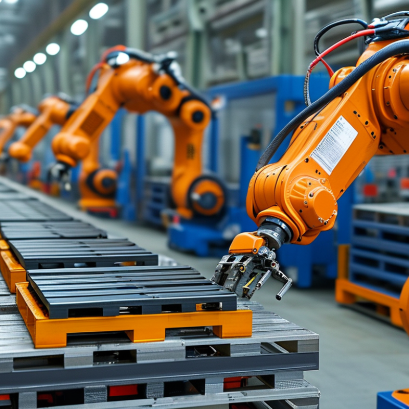
A three-axis servo robot is an automated machine that moves a tool or gripper along three directions: X, Y, and Z. These axes provide horizontal, vertical, and forward-backward movement. Servo motors drive each axis, while encoders report the exact shaft position to a controller. The controller compares the target position with real movement and corrects small errors continuously.
It works through programmed motion coordinates. A sensor may detect a product on a conveyor, then the controller calculates a pickup position. The robot lowers its gripper, closes it, lifts the product, and places it into a tray. Speed, acceleration, payload, and travel distance must match the application. Excessive speed can cause vibration. Poor payload estimates can reduce accuracy.
It is not magic.
When choosing a three-axis servo robot in 2026, examine repeatability, working range, cycle time, safety functions, and maintenance access. A reliable system should provide clear alarms, position feedback, and documented operating limits. Check the actual product weight, including gripper weight and movement forces. That detail is often missed. A robot may appear fast during testing but perform poorly beside a dusty conveyor or uneven work surface. My own evaluation would also question software usability, because complicated programming can create avoidable setup errors. The best choice is not always the fastest model; it is the system that stays accurate, serviceable, and predictable in the real work cell.
| Selection Dimension | Typical Data or Option | How It Works | What to Check Before Purchase |
|---|---|---|---|
| Robot Type | Cartesian or linear robot with 3 servo-driven axes | The X, Y, and Z axes move in straight lines, normally at right angles to one another. Servo motors and feedback devices control position and speed. | Confirm that the required motion is linear and that no wrist rotation or additional orientation axis is needed. |
| Number of Axes | 3 controlled axes: X, Y, and Z | X usually provides horizontal travel, Y provides transverse travel, and Z provides vertical travel. The exact orientation depends on the machine layout. | Add a rotary or end-effector axis if the workpiece must be rotated, tilted, or presented at a changing angle. |
| Servo Feedback | Encoder-based closed-loop control | An encoder reports motor or axis position to the controller, allowing it to correct position errors during motion. | Check encoder resolution, homing method, absolute or incremental feedback, and recovery behavior after power loss. |
| Payload | Approximately 1–50 kg for many industrial configurations, including tooling | The axes and drive system accelerate the end effector, gripper, workpiece, cables, and any process tooling. | Calculate the total moving mass, center of gravity, inertia, acceleration, and safety margin. Do not size the robot from product weight alone. |
| Axis Stroke | Common individual stroke: about 300–3,000 mm; larger custom layouts are possible | Each linear axis travels along a defined guide or rail to reach the required pick, place, inspection, or loading positions. | Measure the complete working envelope, including gripper length, guarding, maintenance access, cable routing, and over-travel limits. |
| Positioning Repeatability | Approximately ±0.01–±0.10 mm in many precision industrial designs | The controller uses feedback and motion profiles to return the axes to programmed positions with limited variation. | Distinguish repeatability from absolute accuracy. Request test results under the intended load, speed, temperature, and installation conditions. |
| Maximum Linear Speed | Roughly 0.5–4.0 m/s, depending on axis, payload, stroke, and mechanics | Servo drives regulate motor speed and acceleration so the robot follows a programmed trajectory without exceeding mechanical limits. | Use the speed at the required payload and stroke, not the no-load maximum. Confirm whether speed is continuous, peak, or axis-specific. |
| Acceleration and Deceleration | Often about 0.5–20 m/s², depending on the axis and load | Motion profiles ramp speed up and down to balance cycle time, vibration, product stability, and mechanical stress. | Verify acceleration with the actual payload, gripping method, product fragility, and required placement accuracy. |
| Cycle Time | Approximately 2–15 seconds for many pick-and-place tasks; application-dependent | A cycle includes movement, gripping or release, settling, process signals, and any dwell time—not only travel time. | Define the full cycle sequence and test it with the real workpiece, tooling, safety interlocks, and upstream/downstream equipment. |
| Drive and Transmission | Servo motor with ball screw, timing belt, rack-and-pinion, or linear motor | The transmission converts motor torque into controlled linear motion. Each mechanism affects speed, stiffness, maintenance, and achievable accuracy. | Match the mechanism to stroke length, contamination level, required stiffness, lubrication conditions, and maintenance capability. |
| Controller Functions | Point-to-point motion, interpolation, recipe storage, diagnostics, and I/O control | The controller coordinates the three axes, executes motion programs, processes sensor signals, and communicates with production equipment. | Check programming method, number of stored programs, remote diagnostics, password control, data backup, and alarm history. |
| Industrial Communication | Digital I/O, Ethernet-based industrial networks, and safety I/O | Communication links the robot with programmable controllers, sensors, vision systems, presses, conveyors, and safety devices. | Select interfaces compatible with the existing control architecture and confirm update, troubleshooting, and cybersecurity procedures. |
| End Effector Compatibility | Mechanical grippers, vacuum tools, magnetic tools, clamps, cutters, or process heads | The end effector performs the actual handling or process operation while the robot supplies position and motion. | Check tool mass, center of gravity, air or electrical utilities, gripping force, changeover time, and sensor feedback. |
| Installation Environment | Standard industrial, clean, dusty, humid, food-related, or washdown environments | Seals, covers, lubrication systems, materials, and cable protection determine resistance to dust, moisture, chemicals, and temperature changes. | Specify ambient temperature, humidity, dust, oil, chemicals, cleaning method, required IP rating, and cleanroom requirements. |
| Safety System | Guarding, interlocked access, emergency stop, safe torque off, and risk-based safety functions | Safety circuits stop or prevent hazardous motion when access doors open, emergency devices are activated, or unsafe conditions are detected. | Perform a machine risk assessment and verify applicable requirements such as ISO 12100, ISO 13849-1, ISO 10218, and IEC 60204-1. |
| Power Requirements | Common industrial supplies include single-phase or three-phase AC systems; voltage and frequency vary by region | The drive amplifiers convert electrical power into controlled motor torque for each axis. | Confirm rated voltage, frequency, peak current, circuit protection, grounding, compressed air needs, and energy recovery requirements. |
| Maintenance Requirements | Rail and screw inspection, lubrication, belt or coupling checks, encoder diagnostics, and cable replacement | Regular service preserves stiffness, repeatability, motion quality, and component life. | Request preventive-maintenance intervals, spare-parts availability, service access, lubrication specifications, and mean-time-to-repair data. |
| Best-Fit Applications | Pick-and-place, machine loading, packaging, palletizing of light products, dispensing, inspection, and assembly | The robot provides repeatable three-dimensional positioning along straight-line paths and can synchronize with production equipment. | Choose another robot architecture if the task needs complex orientation, highly flexible collision avoidance, or many simultaneous rotary movements. |
Note: The numerical ranges are general industrial reference values. Actual performance depends on mechanical design, payload distribution, stroke, acceleration, installation quality, environmental conditions, and the complete application cycle.
© Shipham Valves 2025. All Rights Reserved.
Website By PS Website Design Ltd
Request a Quote/Further Information
Download