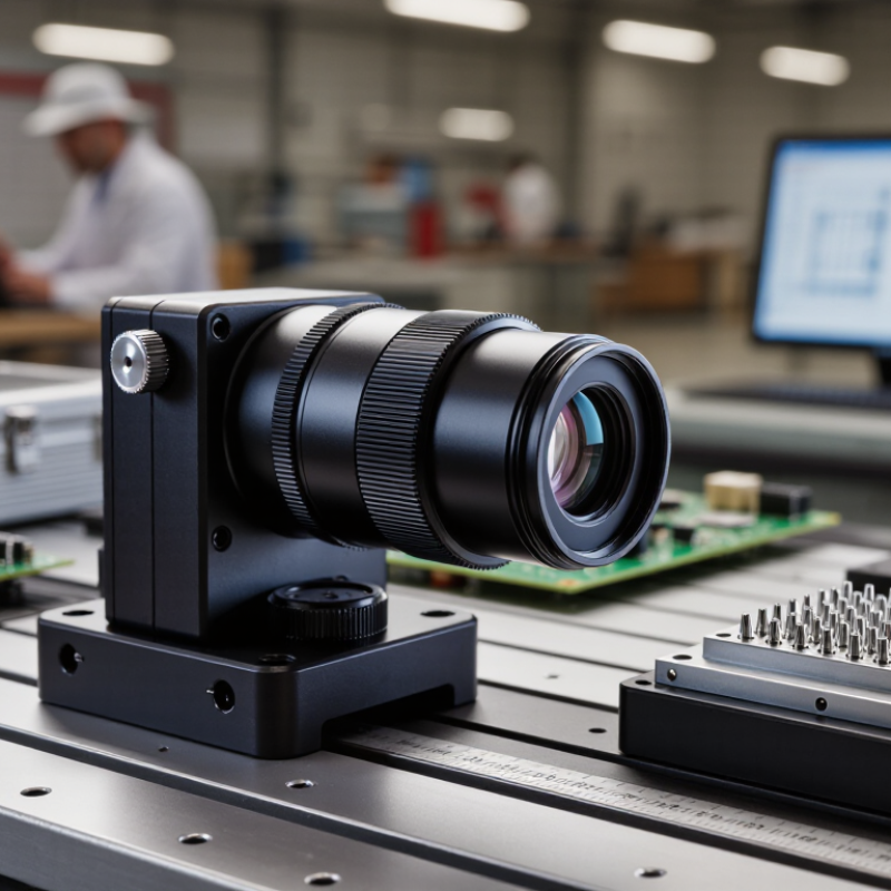
| Optical Definition | A macro lens with telecentric chief rays on the object side, image side, or both | Telecentricity keeps the principal rays approximately parallel to the relevant optical axis, reducing perspective-related dimensional errors. | Choose object-space telecentricity when dimensional accuracy on the inspected object is the primary requirement. |
| Object-Space Telecentricity | Chief-ray angle near 0° in object space | The entrance pupil is positioned at or optically conjugate to infinity, so the apparent size of the object changes very little as its position shifts within the depth of field. | Useful for measuring diameters, widths, hole positions, edge locations, and component profiles. |
| Image-Space Telecentricity | Chief-ray angle near 0° in image space | The exit pupil is positioned at or optically conjugate to infinity, which helps maintain consistent ray angles at the image sensor. | Helpful with sensors whose pixel response varies with incident angle, especially in precision machine-vision systems. |
| Bi-Telecentric Design | Telecentric in both object and image space | Both object-side magnification stability and image-side ray-angle control are optimized. | Typically selected for high-precision gauging, metrology, semiconductor inspection, and dimensional verification. |
| Magnification | Common machine-vision ranges: approximately 0.1× to 1.0×; specialized designs may extend beyond this range | Magnification is the ratio of image size to object size. A value of 0.5× forms an image half the size of the object. | Select magnification from the required field of view and sensor size rather than from working distance alone. |
| Field of View Calculation | Object-side FOV = sensor dimension ÷ magnification | Example: a 6.4 mm-wide sensor used with a 0.5× lens provides an approximate object-side width of 12.8 mm. | Confirm the usable sensor area, optical image circle, and required margin around the inspected part. |
| Working Distance | Often approximately 65–200 mm in industrial configurations; exact values depend on optical design | Working distance is measured from the front reference surface of the lens to the object plane at the specified focus. | Longer working distance provides more room for lighting, fixtures, protective windows, and moving tooling. |
| Depth of Field | Determined by magnification, numerical aperture, permissible blur, and illumination | A smaller numerical aperture generally increases depth of field, while higher magnification and higher resolution requirements tend to reduce it. | Use telecentric illumination and focus-stacking or mechanical height control when the object has significant 3D variation. |
| Distortion | Precision telecentric designs commonly target distortion below 0.1%; exact performance is specification-dependent | Low distortion maintains consistent geometric scale across the image and reduces errors in edge-based measurement. | Always check the measured distortion map at the actual wavelength, working distance, focus, and sensor format. |
| Perspective Error | Substantially reduced compared with conventional entocentric macro lenses | Object size remains more stable when the part moves slightly along the optical axis within the usable depth range. | Telecentricity does not eliminate errors caused by tilt, surface deformation, poor focus, or inadequate calibration. |
| Numerical Aperture | Usually lower than that of many photographic macro lenses at comparable magnification | Lower numerical aperture can support greater depth of field and easier dimensional inspection, but it may reduce light-gathering capability and optical resolution. | Balance resolution, depth of field, exposure time, and illumination power during lens selection. |
| Resolution and Pixel Sampling | Object-space sampling = pixel pitch ÷ magnification | Example: a 5 μm sensor pixel with a 0.5× lens corresponds to approximately 10 μm per object-space pixel. | Sampling alone does not guarantee optical resolution; compare the lens resolution with sensor pixel size and required measurement tolerance. |
| Aperture Control | Fixed or adjustable iris, depending on the lens architecture | Stopping down can improve depth of field and reduce some aberrations, but excessive stopping can introduce diffraction and lower resolution. | Use the smallest aperture that meets the required depth of field without causing unacceptable diffraction blur. |
| Illumination Compatibility | Commonly paired with coaxial, telecentric, dark-field, dome, or backlight illumination | Telecentric backlighting is especially effective for producing stable silhouettes and high-contrast edges in dimensional inspection. | Match illumination geometry to the surface finish, transparency, reflectivity, and measurement feature of the part. |
| Spectral Range | Visible designs commonly operate around 400–700 nm; near-infrared variants may extend into approximately 850–1,000 nm | Optical correction, focus position, transmission, and chromatic aberration depend on the operating wavelength. | Specify the lighting wavelength and verify monochromatic or broadband performance before finalizing the optical system. |
| Sensor Compatibility | Specified by image circle, sensor format, magnification, and mounting interface | The image circle must fully cover the active sensor area to avoid corner shading or loss of usable pixels. | Check sensor diagonal, flange distance, mount thread, camera clearance, and mechanical envelope. |
| Typical Applications | Dimensional gauging, connector inspection, PCB component inspection, semiconductor packaging, glass inspection, and pharmaceutical components | These applications benefit from stable magnification, low distortion, sharp edge definition, and controlled perspective. | For reflective or transparent objects, evaluate glare control, polarization, backlighting, and coating performance in addition to lens specifications. |
| Calibration Requirement | Recommended even with a telecentric lens | Calibration compensates for residual distortion, pixel scale, sensor alignment, and system-level mechanical tolerances. | Use a certified calibration target appropriate to the required accuracy and calibrate at the same focus, magnification, and lighting conditions used in production. |
| Key Limitations | Larger diameter, higher mass, narrower field coverage, and often higher cost than conventional macro lenses | The front optical group and telecentric stop arrangement require additional glass, space, and mechanical precision. | Confirm that the camera, lighting, robot, fixture, and machine frame can support the lens size and working distance. |
| Manufacturer Evaluation Criteria | Verified optical specifications, repeatable production quality, calibration support, customization capability, and quality documentation | A reliable supplier should provide measured data for magnification, distortion, telecentricity, resolution, working distance, and image-circle coverage. | Request optical test reports, sample images, tolerance data, coating information, environmental specifications, and after-sales engineering support. |