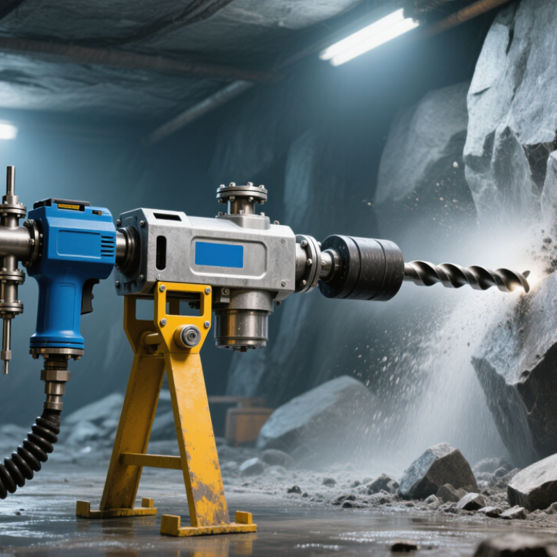
Choosing the 2026 Best S83 Pneumatic Air Leg Rock Drill requires more than comparing catalog prices. Underground drilling conditions vary sharply. Hard granite, fractured limestone, and wet headings demand different operating decisions. The right machine must match the rock, hole diameter, drilling depth, and available air pressure.
Dr. Evert Hoek, a leading rock mechanics expert, stated, “The objective of rock engineering is to design structures that are safe and economical.” That principle also guides pneumatic drill selection. An S83 model should deliver stable penetration without excessive vibration. Its air-leg response matters when the operator adjusts drilling height. A reliable water-flushing system can reduce dust and improve bit performance. Small details matter underground.
Look for a durable piston, accessible valves, corrosion-resistant fittings, and straightforward maintenance points. Check the manufacturer’s rated air consumption carefully. A compressor that seems adequate on paper may lose pressure through long hoses, leaks, or multiple working faces. That mistake is common. Noise and operator fatigue also deserve attention, even when production targets dominate the discussion.
This guide compares practical S83 pneumatic air leg rock drill factors, including drilling efficiency, serviceability, safety features, and total operating cost. Performance claims should be tested against real site records, not attractive brochures. Some specifications may still require confirmation from the supplier. That is worth admitting. A drill can look powerful in a workshop and perform poorly in a cramped, dusty heading. The best choice is the one that remains controllable, repairable, and productive during ordinary shifts.
An S83 pneumatic air leg rock drill is built around an 83 mm cylinder, a specification that influences impact stability and drilling control. In underground work, this size can provide useful power for medium-hard rock faces. The drill also requires 0.63 MPa air pressure for proper operation.
During field checks, operators should measure pressure at the drill inlet, not only at the compressor. Long hoses, narrow fittings, and leaking connections can reduce delivered pressure. At 0.63 MPa, the air leg should extend smoothly and hold the drill firmly against the rock.
A jerky feed often indicates restricted airflow, worn seals, or poor alignment. The 83 mm cylinder does not correct these problems.
Practical maintenance includes cleaning the air line, draining moisture, checking lubrication, and inspecting the drill steel before each shift. A damaged bit can increase vibration and waste compressed air.
Workers should also confirm the drill’s weight, hose length, and rock condition before choosing it for a mining task. My field experience suggests that pressure readings alone can mislead; airflow volume and connection quality matter just as much.
One limitation deserves attention.
Performance may fall noticeably in cold, wet, or poorly ventilated headings.
Maintenance records, operator training, and site testing provide stronger evidence than specifications printed on paper.
In underground headings, an S83 pneumatic air leg rock drill is judged by usable output, not catalog numbers. The key working range is 34–42 mm holes, paired with a 30–40 Hz impact frequency. This frequency helps maintain steady energy transfer through hard rock, but performance changes with air pressure, feed force, and bit condition. Field measurements matter more than advertised capacity.
A 34 mm hole may advance faster when the formation is compact and uniform. A 42 mm hole can improve clearance for blasting patterns, yet it usually demands greater torque and airflow. Small differences become visible at the face.
Watch the drill steel, listen for irregular impact, and check whether the air leg holds stable contact. Poor alignment can increase hole deviation and waste drilling time.
In practical testing, operators should record penetration rate, pressure, vibration, and bit wear for each hole. The 30–40 Hz range is useful, though maximum frequency is not always best. Excessive vibration may reduce control and fatigue the operator. I would not call every 42 mm hole efficient. That assumption often fails in fractured rock. A reliable assessment also includes maintenance intervals, lubrication quality, and actual compressor output. Clean data reveals whether the drill is productive or merely working loudly.
An S83 pneumatic air-leg rock drill needs a stable air supply to work effectively underground. Its typical consumption ranges from 3 to 5 m³/min, depending on drilling pressure, rock hardness, and operating habits. A practical compressor test should measure flow at the drill, not only at the compressor outlet. Pressure loss through long hoses can quietly reduce performance.
Feed force also matters. Excessive force can slow rotation, increase bit wear, and damage the drill mechanism. Too little force may cause bouncing, uneven holes, and wasted air. Experienced operators usually adjust the feed until the bit cuts smoothly without harsh vibration. The exact setting changes with rock conditions. There is no universal number.
Tips: Use a clean, correctly sized air hose. Check couplings before every shift. Drain moisture from the air system. Keep the feed leg aligned with the drilling angle. Listen for unusual exhaust sounds. Small noises can reveal larger problems.
Field inspections often show a simple mistake: the drill is blamed when the compressor system is undersized. Measuring air flow, hose pressure, and feed response together gives a more reliable diagnosis. However, these checks should follow the equipment manual and site procedures. I would not choose a drill based on consumption alone. Service access, operator control, and replacement parts can matter just as much. Some performance expectations may also be optimistic. Testing on the actual rock remains the better decision.
A 2026 S83 pneumatic air leg rock drill should be evaluated at the working face, not only in a catalog. A stable 7 bar supply equals 0.7 MPa, but pressure losses can occur through long hoses, couplings, filters, and undersized valves. Measure pressure while drilling. Static readings can mislead operators. ISO 4414 emphasizes pressure control, isolation, and safe maintenance for pneumatic systems. The line should also have a reliable regulator, water separator, and emergency shutoff. Air quality matters. Moisture can damage internal components and weaken lubrication. Experienced crews inspect hose connections before every shift. Small leaks become serious during continuous drilling.
Lubrication must match the drill’s service instructions. Use a clean, compatible pneumatic oil through a calibrated oiler. Too much oil is not better. Excess oil may contaminate the workplace and attract abrasive dust. Dust control requires equal attention. OSHA’s respirable crystalline silica rule sets a 50 micrograms per cubic meter, eight-hour exposure limit, with a 25 micrograms action level. The NIOSH and Industrial Minerals Association North America Dust Control Handbook, second edition, 2019, recommends wet drilling, effective ventilation, and enclosure where practical. Water flow should reach the bit, not merely the hose exterior. Operators still need exposure monitoring and suitable respiratory protection. One weakness remains: wet methods can reduce visibility and create slippery ground. Good mining practice must manage both hazards.
Technical selection and safe-operation reference for an S83-class pneumatic air-leg rock drill. Values marked “typical” must be confirmed against the selected drill, air leg, hose, and local regulations.
| Data Dimension | Typical / Recommended Value | Mining Application and Safety Significance |
|---|---|---|
| Equipment and Performance Reference | ||
| Drill category | Hand-held pneumatic rock drill with air leg | Designed for underground development, drifting, quarrying, and small-to-medium blast-hole work where compressed air is available. |
| Nominal air pressure | 7 bar / 0.70 MPa / approximately 102 psi | Use a regulated supply close to the drill manufacturer’s specified operating pressure. Pressure must not exceed the lowest-rated component in the complete air system. |
| Typical air consumption | Approximately 60–75 L/s at rated pressure | Size the compressor, receiver, filters, valves, and hose for continuous demand. Actual consumption varies with drill condition, drilling resistance, pressure, and control-valve setting. |
| Typical impact frequency | Approximately 2,000–3,000 blows/min | Higher impact frequency does not automatically mean better drilling. Maintain sharp bits, correct feed force, and stable air pressure to control vibration and tool wear. |
| Typical drill-steel compatibility | Commonly 22 mm shank systems; verify the exact shank standard | The bit, shank, bushing, and chuck must be matched. Incorrect shank dimensions can cause poor energy transfer, premature wear, or ejection hazards. |
| Typical hole diameter range | Approximately 34–42 mm, depending on bit and rock conditions | Hole size depends on bit geometry, rock strength, fracture pattern, and the planned blasting method. Confirm the required diameter with the mine plan. |
| Typical stroke | Approximately 60 mm | A stroke near this range is common for S83-class pneumatic drills, but the actual value should be checked in the equipment manual before selecting drill steel. |
| Approximate drill mass | Approximately 23–27 kg for the drill body; air-leg mass is additional | Assess total handling weight, operator posture, mounting height, and lifting arrangements. Use mechanical assistance where manual handling creates an injury risk. |
| Rotation system | Pneumatic rotation; speed varies by design and load | Rotation must remain smooth without binding. Stop the drill before clearing a jam, changing steel, or placing hands near the chuck. |
| 7 bar Air-Line Design and Inspection | ||
| Supply-pressure control | Regulator set to the equipment specification; nominal reference: 7 bar | Install a pressure regulator and gauge at the working area. Do not compensate for undersized hoses by raising pressure above the approved limit. |
| Hose working-pressure rating | At least the maximum system pressure | Select air hose, couplings, valves, and whip-check devices with compatible pressure ratings. The assembly rating is limited by its lowest-rated part. |
| Hose sizing | Use the manufacturer’s airflow table; avoid unnecessarily long or narrow hose | Pressure drop increases with length, small internal diameter, restrictive couplings, bends, and clogged filters. Measure pressure at the drill, not only at the compressor. |
| Couplings and hose restraint | Positive-lock couplings with safety clips and whip checks | Secure connections against accidental separation. Never connect or disconnect a pressurized hose, and never carry a pneumatic drill by its hose. |
| Condensate management | Drain receivers, low points, filters, and separators routinely | Water in the air line can wash lubricant from the motor, promote corrosion, freeze in cold conditions, and reduce drilling performance. |
| Pre-start air-line inspection | Every shift and after relocation | Check hose cuts, bulges, abrasion, coupling damage, gauge function, regulator setting, valve operation, and visible leaks before energizing the drill. |
| Lubrication and Maintenance Controls | ||
| Air-line lubricator | Install an inline pneumatic oiler close to the drill where permitted | Use the lubricant specified for the drill and mine environment. A lubricator should be installed in the correct airflow direction and kept filled only when the line is isolated. |
| Lubrication quantity | Set according to the equipment manual; do not use a universal fixed dose | Too little oil accelerates vane, piston, and cylinder wear. Too much oil can contaminate the workplace, increase consumption, and create unnecessary slip or exposure hazards. |
| Manual oiling | Use only the approved procedure when an automatic oiler is unavailable | Isolate and depressurize the line before adding oil. Never pour oil into a live coupling or place fingers near an open air outlet. |
| Lubricant selection | Use pneumatic-tool oil compatible with seals and the mine’s environmental requirements | Do not substitute gasoline, diesel, brake fluid, or incompatible solvents. Store lubricant in labeled containers and manage spills promptly. |
| Maintenance interval | Daily inspection; scheduled service based on operating hours and condition | Inspect the chuck, bushing, shank, water ports, air leg, fasteners, and controls. Remove the drill from service if abnormal noise, excessive vibration, leakage, or reduced impact occurs. |
| Dust Control, Water, and Worker Protection | ||
| Preferred drilling method | Wet drilling with water injection | Water reduces airborne respirable dust at the bit. Confirm that the drill is designed for water flushing and that the water circuit is clean and correctly connected. |
| Water pressure | Maintain positive water pressure at the drill; follow the equipment manual | Water pressure should be sufficient to prevent dust blowback and clear cuttings without damaging seals or creating uncontrolled spray. Do not assume air pressure and water pressure are interchangeable. |
| Dry drilling | Use only where permitted and with engineered dust extraction or suppression | Dry drilling can generate respirable crystalline silica and other hazardous dust. Apply the mine’s dust-control plan and use suitable respiratory protection where required by risk assessment. |
| Ventilation | Maintain the approved mine ventilation quantity and direction | Ventilation must control dust, diesel pollutants, and exhaust air without directing contaminated air toward workers. Do not rely on ventilation alone to control drilling dust. |
| Respiratory protection | Use a fit-tested respirator when required by exposure assessment | Respirators supplement, but do not replace, wet drilling, local exhaust, enclosure, housekeeping, and exposure monitoring controls. |
| Noise and vibration | Use hearing protection and manage hand-arm vibration exposure | Record measured noise and vibration where required. Rotate tasks, maintain tools, keep a firm but non-excessive grip, and follow the site’s exposure limits and rest schedule. |
| Personal protective equipment | Helmet, eye protection, hearing protection, protective footwear, gloves, and task-appropriate respiratory protection | Gloves must not create an entanglement risk around rotating components. Keep clothing, hair, and loose items away from the chuck and air leg. |
| Selection Checklist for a 2026 Mining Purchase | ||
| Air-system compatibility | Pass / verify | Confirm the mine can deliver the required flow at approximately 7 bar at the drill, including simultaneous users and expected pressure losses. |
| Dust-control compatibility | Pass / verify | Confirm water-injection capability, water quality, flushing arrangement, drainage, and compatibility with the site dust-management plan. |
| Operator ergonomics | Pass / verify | Assess air-leg adjustment range, drilling height, total mass, control placement, vibration, noise, and access in the actual working envelope. |
| Compliance documentation | Required before deployment | Obtain the operating manual, maintenance schedule, pressure and flow data, hose/coupling requirements, risk assessment, inspection records, and applicable local mining approvals. |
| Emergency isolation | Required | Provide a clearly accessible shut-off valve, isolate and bleed the line before service, and apply the mine’s lockout/tagout procedure. |
2026 Best S83 Pneumatic Air Leg Rock Drill for Mining?
Selecting the best S83 pneumatic air leg rock drill requires more than comparing catalog prices. Measure the complete working weight, including the leg, hose, chuck, and lubricator. A lighter unit is easier to reposition underground. However, excessive lightness may reduce stability in hard rock. Confirm the S83 shank drawing and collar dimensions before ordering. Labels alone can mislead.
Service life should be measured in drilled meters, not operating hours. Request test results from comparable rock, hole diameter, air pressure, and bit type. Record striker wear, piston replacement intervals, and leg seal failures. The European vibration directive sets an action value of 2.5 m/s² and a limit value of 5 m/s² for hand-arm exposure. Actual exposure depends on operation and maintenance. That detail is often overlooked.
Cost per meter offers a clearer comparison. Use this formula: purchase cost, consumables, compressed air, labor, repairs, and downtime, divided by completed meters. The U.S. Department of Energy’s compressed-air sourcebook reports that leakage can waste 20–30% of compressor output. Poor hoses can quietly inflate drilling costs. Ask for air consumption at the intended pressure, then verify it with a flow meter onsite. I would not trust a low purchase price without field records. A short trial may reveal unstable feeding, excessive vibration, or slow penetration. That uncertainty deserves a budget.
Representative industry benchmarks for S83-class pneumatic air-leg rock drills. Values vary with rock hardness, operating pressure, drill steel quality, maintenance, and local labor costs.
A practical S83-class drill commonly weighs about 38–45 kg and uses a 22 × 108 mm or 25 × 108 mm shank system. Longer service life and lower drilling cost per meter generally require stronger components, correct air pressure, sharp drill bits, and regular lubrication.
© Shipham Valves 2025. All Rights Reserved.
Website By PS Website Design Ltd
Request a Quote/Further Information
Download
We use cookies on this website, by continuing to browse the site you are agreeing to our use of cookies. Find out more.